Woody Island: Microstructure of S2
|
Table 1 Abbreviations used for various foliations. "External" and "internal" refer to foliations outside and inside of the shale clasts. S2 is the general cleavage as seen in hand specimen or outcrop, made up of a combination of S2e and S2i. |
In finer grained sandy and silty layers the foliation is commonly penetrative with most micas oriented parallel to the axial plane cleavage, or it is domainal, and defined primarily by anastomosing films composed mainly of elongate mica grains, oriented with (001) parallel to the film. As a consequence of the anastomosing nature of the films many of the domainal fabrics are bimodal. In addition there is commonly a third orientation group comprising sparse mica grains within the film-bounded lenticular domains. These micas are aligned approximately perpendicular to the cleavage and in contrast to the micas in the films they are elongate perpendicular to (001) (stacks of Voll, 1960; for a review see also van der Pluijm and Kaars-Sijpesteijn, 1984). They are believed to have grown on detrital micas (e.g. Hoeppener, 1956). In the most pelitic rocks the foliation may be a crenulation cleavage which may or may not be differentiated.
The penetrative foliation is most common in incompetent layers on the concave side of folds in competent layers, but may occur in all parts of tight folds. It is least common on the convex side of folds in competent layers. Bimodal fabric and crenulation cleavage are generally more common than penetrative foliation and are particularly common on the convex side of folds in competent layers. Where the fabric is clearly bimodal, relic kinks or crenulations are generally present in the mica.
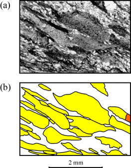
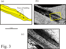
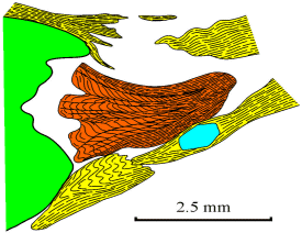
It is the shale clast bearing units that are particularly interesting from a cleavage development point of view. They include not only the units that contain clasts clearly recognisable in hand specimen, but also the unit previously referred to as mélange (Pajari et al., 1979). In the field the mélange appears to be a poorly sorted, fine grained rock with blocks of sandstone floating in the fine grained matrix, but in thin section the "matrix" is seen to be composed almost entirely of shale clasts in a sparse sandy or silty matrix (Fig. 2) (Williams, 1983). The shale clasts are recognisable in thin section because of variation in their, layersilicate, iron oxide and carbon content (Fig. 2), but this variation combined with their small grain size (generally between 0.5 and 5 mm) is insufficient to render the clasts visible in hand specimen. There is a compositional layering, presumably bedding, within many of the clasts (Fig. 3), which is also due to variation in layersilicate, iron oxide and carbon content. The S2 foliation in these rocks is defined not only by the preferred orientation of shale clasts and matrix grains, but also by anastomosing mica-films in the matrix and by a foliation within the clasts. This "internal S2 foliation" (S2i) varies in nature in adjacent clasts, from symmetrical to asymmetrical crenulation cleavage, to a penetrative foliation. There is an obvious correlation between the shape of the clasts, the orientation of bedding where recognisable, the magnitude of strain and the nature of the foliation. The salient relationships are summarised below.
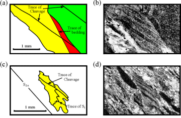
In most clasts that are recognisably layered there is a foliation defined by the preferred orientation of mica parallel to layering (Fig. 3b) and in the exceptions there is a similar foliation at a high angle to layering which shows evidence of being a transposition foliation. The layer-parallel fabric is typical of shales (e.g. Hobbs et al., 1976, p.153; Siddans, 1976) and like the layering is interpreted as a bedding feature (Ssi). Though defined now by metamorphic mica it is believed to be mimetic after a sedimentary layersilicate fabric. The possibility that this internal foliation (Si) is a metamorphic fabric related to F1 folds is eliminated because in all but the most strongly deformed clasts, Si is parallel to bedding within the clast (Ssi) and where they are not crenulated both are parallel to the long dimension of the clast. In summary, the mica fabric within the clasts is either parallel to bedding (Ssi), or, if inclined to bedding, is seen to be a product of micro-scale transposition of an earlier foliation (i.e. it is S2i). In the less transposed examples, this earlier foliation is seen to be parallel to (Ssi), and is therefore interpreted as Si.
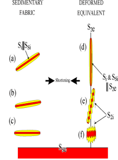
The morphology of the bedded clasts is described below. Three end-member morphologies are recognised, based on the orientation of compositional bedding within the clasts (Ssi), relative to the long dimension of the clasts and S2i (Fig. 4d, e & f). To facilitate description, the clasts are grouped according to their resemblance to one of the end-members, but it should be noted that there is a seamless gradation in morphology, between members of the three groups.
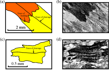
The first end-member is characterised by S2i perpendicular to compositional bedding (Ssi)(Fig. 4f). In these clasts, both Ssi and Si are generally crenulated into a symmetrical differentiated crenulation cleavage (Fig. 5). This cleavage (S2i) is parallel to S2e in the surrounding rock (Fig. 4f). Clast outlines tend to be fairly equant with aspect ratios commonly less than 2:1 (e.g. Fig. 5c & d) and the long dimension commonly approximately parallel to S2e (Fig. 5), but locally approximately perpendicular to S2e. Outlines tend to be irregular or visibly folded (Fig. 5c & d). Locally, S2i in these clasts is a penetrative foliation very much like Si, but generally there is some evidence of crenulations preserved. Intermediate stages in the development of the transposed foliation show that tightening of crenulations is the main process involved, but in some clasts (e.g. Fig. 6), the intermediate stages preserved within a single microlithon indicate that transposition has occurred by unfolding of crenulations (cf. Williams and Schoneveld, 1981). Which process occurs, depends on whether adjacent limbs of crenulations have the same (unfolding) or opposite (tightening of folds) sense of rotation. This in turn depends on the initial tightness of the crenulations and their orientation with respect to the shortening direction.
The second end-member (Fig. 4e), has an asymmetrical differentiated crenulation cleavage (S2i) (Fig. 7) which is inclined to the length of the clast, Ssi and S2e. The long dimension of the clast is parallel to Ssi and is also generally inclined to S2e. S2i either lies between the long dimension and S2e or the long dimension and S2i are symmetrically disposed about S2e (Fig. 4e). The clasts are generally elongate with aspect ratios commonly in excess of 3:1 and clast outlines may be asymmetrically crenulated, but tend to be smoother than those of the first group. On fold limbs the crenulation cleavage in these clasts is generally antithetic with respect to the fold. There are exceptional cases where the cleavage is synthetic, but there are insufficient observations to generalise on the orientation of such clasts and their cleavage, other than to say that they are approximately parallel to S2.
The third end-member (Fig. 4d.) lacks any evidence of crenulation cleavage. Ssi, Si and the long dimension of the clasts are all parallel and are approximately parallel to S2e. Si in such clasts is truly penetrative and shows no evidence of having developed by transposition (Fig. 3c), since there are no relic folds. These clasts are the most elongate with aspects ratios commonly in excess of 4:1, and have the smoothest outlines.
Most clasts lack compositional bedding (Ssi), but otherwise exhibit exactly the same range of microstructures, aspect ratios, outlines and orientations as describe above. The only difference is the lack of bedding.
In a fold hinge the first end-member type (Fig. 4f) is the most abundant but all three groups are present. On the fold limbs it is the least abundant and the third type (Fig. 4d) is slightly more abundant than the second (Fig. 4e).
