FLOW IN POLYCRYSTALLINE ICE
Part 2 - Background information
By Chris Wilson and Brett Marmo
2.8 Basal glide
Ice Ih readily undergoes plastic deformation if a component of shear stress acts on the basal plane (McConnell 1891; Kamb 1961). The ease of this style of deformation is due to the slip or glide across the basal plane. Slip along the basal plane is facilitated by the movement of dislocations through the G-planes of the lattice. The orientation of the crystal within a stress regime defines how and if the crystal deforms. Nakaya (1958) performed a series of experiments by applying a loaded wedge to the centres of ice crystals that were supported at each end by stationary wedges (Fig. 2.8.1). When the wedge was applied parallel to the basal plane, glide occurs readily and is localised close to the applied stress (Fig. 2.8.1a). When the wedge is applied at 45° to the basal plane, again glide occurred and the crystal bowed (Fig. 2.8.1b). These two orientations are referred to as easy glide orientations. When the load was applied (1) perpendicular to the basal plane little deformation occurred and the crystal kinked to form a V-shape (Fig. 2.8.1c) and (2) perpendicular to the c-axis and parallel to the basal plane then negligible deformations occurred (Fig. 2.8.1d). These orientations are referred to as hard glide orientations. Little deformation occurred because there was no component of shear stress along the basal plane.
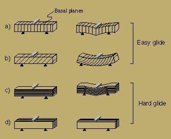
Figure 2.8.1: When a cantilever is applied to a single crystal of ice the deformation style is dependent on the orientation of the basal plane relative to the load. Both a) and b) are in easy glide orientations, such that a shear stress is resolved onto the basal plane. These deform readily when a stress is applied. c) and d) are in hard-glide orientations where no shear stress is resolved onto the basal plane. These are very resistant to deformation.
2.9 Strain rate for glide on basal systems
Ice Ih experiences work softening when a shear stress is applied across its basal plane over a prolonged period of time Glen & Perutz (1954), Steinemann (1954), Griggs & Cole (1954), Rigsby (1957). That is, the strain rate increases with time. This process is unusual as most solids work harden during basal glide. Griggs & Cole (1954) applied compressive stress at 45° to the c-axis of ice crystals between -10°C and -11°C (Fig. 2.9.1). The creep curves can be described by:
![]() ----------------------------------------equation
(2)
----------------------------------------equation
(2)
where ![]() is the compressive strain as a percentage,
is the compressive strain as a percentage, ![]() the compressive stress in bars,
the compressive stress in bars, ![]() the
temperature in °C below the melting point, and t the time in
hours.
the
temperature in °C below the melting point, and t the time in
hours.
Steinemann (1954) applied varied shear stresses
to the basal planes of ice crystals. His results showed a slow strain
rate for the first 20% of strain (primary strain), then a rapid increase
(Fig. 2.9.1). For long periods of time the
strain rate eventually becomes constant. At a temperature of -2.3°C
the shear strain rate, ![]() ,
was related to the shear stress,
,
was related to the shear stress, ![]() ,
by:
,
by:
![]() ----------------------------------------equation
(3)
----------------------------------------equation
(3)
where A is a temperature dependent constant and n is a constant between 1.3 and 1.8 for large strains and 2.3 and 4 for the primary strain.
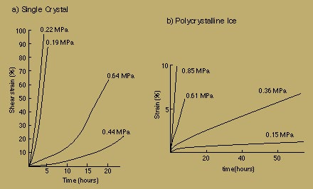
Figure 2.9.1: Creep curves in ice. a) The variation in strain in a single crystal under a constant applied stress. Single crystals exhibit strain softening when glide occurs on the basal plane. The strain rate initially increases with time until a constant strain rate is reached (After Griggs and Cole, 1954). b) Polycrystalline ice under a constant stress, the initial deformation is rapid, strain hardens, then slows with time until it reaches a constant strain rate (After Glen, 1955).
Wakahama (1962) performed extensive deformation
experiments on glacial ice. Tensile and compressive stresses applied to
plates of ice at -10°C, where the c-axes of crystals were contained
within the plane. Stress was applied at between 20° and 45° to
the c-axis at constant strain rate and a schematic stress-time
curve was developed from the experimental results (Fig. 2.8.2). When the
shear strain rate was greater that 12% per hour the stress rises quickly
from O to A, then drops sharply due to a cleavage fracture occurring on
the basal plane. At low strain rates of 3% per hour, the stress followed
a curve OBC. At B the yield stress, ![]() ,
was obtained at which point the ice was able to creep at a constant rate
without increasing the shear stress. The magnitude of the yield stress
increases with strain rate. Results show that:
,
was obtained at which point the ice was able to creep at a constant rate
without increasing the shear stress. The magnitude of the yield stress
increases with strain rate. Results show that:
![]() ----------------------------------------equation
(4)
----------------------------------------equation
(4)
where ![]() is the shear strain rate as a percentage per second,
is the shear strain rate as a percentage per second, ![]() the shear stress in bars, and
the shear stress in bars, and ![]() is
the critical stress, which is defined as the smallest stress required
to initiate slip on the basal plane. The critical stress for ice at -10°C
is ~0.02 MPa.
is
the critical stress, which is defined as the smallest stress required
to initiate slip on the basal plane. The critical stress for ice at -10°C
is ~0.02 MPa.
With the strain kept constant after C, the stress relaxed along CD, according to:
![]() ----------------------------------------equation
(5)
----------------------------------------equation
(5)
where t is the time measured from
the moment the strain was stopped, ![]() and
and ![]() are the shear stress at time 0 and t
respectively. Relaxation stress was also observed
when strain was stopped during the primary deformation (OB). The stress
relaxed more slowly if the strain was stopped earlier in the deformation.
are the shear stress at time 0 and t
respectively. Relaxation stress was also observed
when strain was stopped during the primary deformation (OB). The stress
relaxed more slowly if the strain was stopped earlier in the deformation.
Wakahama (1962) assumed that dislocations
were initiated and renewed as Frank-Read sources (Fig.
2.5.1). The internal Frank-Read sources lie at different distances
from the periphery on the crystal. When a stress is applied to the basal
plane, all the sources that have a length that satisfy`![]() will begin to create dislocation loops. From theory and observation, when
will begin to create dislocation loops. From theory and observation, when
 ,
the velocity,
,
the velocity, ![]() ,
of a dislocation moving through ice at -10°C is given by:
,
of a dislocation moving through ice at -10°C is given by:
![]() ----------------------------------------equation
(6)
----------------------------------------equation
(6)
where the constant is ![]() .
The maximum stress that the basal plane of ice can withstand without fracturing
is ~2 MPa. At 2 MPa across the basal plane, the velocity of a dislocation
is
.
The maximum stress that the basal plane of ice can withstand without fracturing
is ~2 MPa. At 2 MPa across the basal plane, the velocity of a dislocation
is ![]() .
This is much slower than for other materials such as metals that have
a velocity in the order of
.
This is much slower than for other materials such as metals that have
a velocity in the order of ![]() (Hobbs 1974). The dislocation loops therefore take some time to reach
the surface of the crystal. When the stress is initially applied, the
dislocations created from sources close to the surface of the crystal
will propagate to the edge first and a small amount of strain will be
observed. Over time dislocations created from deeper in the crystal will
emerge and their contribution to strain will be summed with those that
continue to be created close to the crystal's edge, resulting in an increase
in strain rate, hence strain softening. Eventually dislocations formed
at the center of the crystal will emerge at the edge so that all the Frank-Read
sources appear to be contributing to the strain. From this point on the
strain rate will be constant with respect to time.
(Hobbs 1974). The dislocation loops therefore take some time to reach
the surface of the crystal. When the stress is initially applied, the
dislocations created from sources close to the surface of the crystal
will propagate to the edge first and a small amount of strain will be
observed. Over time dislocations created from deeper in the crystal will
emerge and their contribution to strain will be summed with those that
continue to be created close to the crystal's edge, resulting in an increase
in strain rate, hence strain softening. Eventually dislocations formed
at the center of the crystal will emerge at the edge so that all the Frank-Read
sources appear to be contributing to the strain. From this point on the
strain rate will be constant with respect to time.
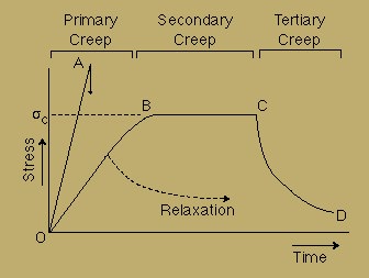
Figure 2.9.2: A schematic sketch of stress-time curve for deformation in a single crystal of ice at -10°C (After Wakahama, 1962).
Weertman (1963) applied steady state motion
of visco-elastic materials theory, developed by Schoeck (1956) and Eshelby
(1961), to explain creep features in ice. The stress field around a dislocation
induces order around the moving dislocation. This reorients protons within
the lattice and acts as a viscous drag on the motion of dislocations.
If steady state creep is controlled by this mechanism, then the maximum
shear strain rate, ![]() ,
is given by:
,
is given by:
 ----------------------------------------equation
(7)
----------------------------------------equation
(7)
where ![]() is the maximum value of the logarithmic decrement of the internal friction
peak,
is the maximum value of the logarithmic decrement of the internal friction
peak, ![]() the average mechanical relaxation time and G the average shear
modulus,
the average mechanical relaxation time and G the average shear
modulus, ![]() the shear stress on the slip plane and n has the value of 3. This
is the same form as the equation deduced by Steinemann (1954) from experimental
deformation (
the shear stress on the slip plane and n has the value of 3. This
is the same form as the equation deduced by Steinemann (1954) from experimental
deformation (![]() ).
From easy glide experiments at -2°C and 0.1 MPa on the slip plane,
).
From easy glide experiments at -2°C and 0.1 MPa on the slip plane,
![]() ,
,
![]() and
and ![]() .
When these values are substituted into equation 6 the steady state creep
rate equals
.
When these values are substituted into equation 6 the steady state creep
rate equals ![]() .
.
Weertman (1963) also suggests that creep may occur via dislocation climb. This process is much slower than basal glide. It involves the transport of water molecules from the extra half plane of the dislocation to a plane perpendicular to the glide plane. Climb occurs progressively by the migration of jogs on the dislocation. The activation energy for glide controlled by climb in ice is 0.57 eV (Hobbs 1974).