The basics of Darcian or advective flow through a permeable medium are described in Darcy’s equation for one-dimensional flow:
| Q = - A · K · Df/Dx | (A.1) |
This equation states that the flow rate, Q (m3 s-1), along a line in the x-direction, is linearly proportional to the cross-sectional area, A (m2), through which the fluid flows, the hydraulic conductivity, K (m s-1), and the gradient in hydraulic head, Df/Dx (m/m). A more general three-dimensional form of Darcy’s equation is:
| q = - K · df/dx | (A.2) |
where the vector q (m s-1) is the rate of flow, per cross-sectional unit area, in the direction x.
Hydraulic head is often confused with pressure when it is stated that "fluid flows from high to low pressure". Obviously, it is not so simple as water does not flow from the bottom of a glass (highest P) to the surface (lowest P). The hydraulic head (unit is metre) is given by:
| f = P / rg + z | (A.3) |
The first part of the equation is the pressure head, determined by the
pressure, P (Pa), the fluid density, r (kg m-3),
and the gravitational acceleration constant, g (m s-2).
The second term, z (m), is the elevation head, which is simply the elevation
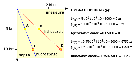
above some datum level. If the pressure is simply the hydrostatic pressure,
then the hydraulic head is the same at any level. If fluid pressure increase
with depth is equal to the lithostatic pressure gradient (say 2.75·104
Pa/m), then the hydraulic head gradient is 1.75 and fluid would flow upwards
(Fig. A1).
The hydraulic conductivity inside an open fluid reservoir is infinite
and hence the hydraulic head inside a water-filled fracture is the same
at any level in that fracture. As a consequence, the pressure inside such
a fracture increases by about 104 Pa/m
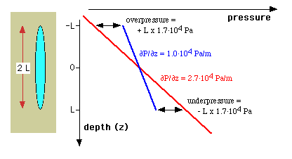
with depth. Suppose now that we have a vertical fracture of length 2L that
is filled with water (r~1·103
kg/m3) in a surrounding rock with a density
of 2.7·103 kg/m3
(Fig. A2). It is clear that the vertical pressure gradient inside the fracture
(1.0·104 Pa/m) is different from
the pressure gradient in the adjacent rock (2.7·104
Pa/m). Suppose now that the pressures balance halfway the fracture, which
level we take as a reference (z=0 m). At the upper tip of the fracture,
the fluid pressure exceeds the rock pressure by L · 1.7·104
Pa. The fluid is underpressured with respect to the rock pressure by the
same amount at the bottom end of the fracture. This puts a limit on the
length of an open fluid-filled fracture. Above some critical length, the
overpressure at the upper end of the fracture causes the rock to further
split open, while the underpressure causes the fracture to be closed at
the bottom end. If the fluid volume is to remain constant, opening and
closure must occur in tandem and when this happens the fracture moves
upwards together with its fluid.
Secor & Pollard (1975) provided a simple equation to estimate the onset mobility of a vertical fracture:
| Lmax = 1.36 · (Kc/S)2/3 | (A.4) |
Lmax is the maximum length of a stable fracture, Kc is the fracture toughness and S is the effective normal stress gradient (S = dr / dz, ~ 0.015 MPa/m). The fracture toughness is about 1-3 Mpa·m1/2 for intact crystalline rocks (granite, gneiss; Secor & Pollard 1975), but is probably lower for schists and low grade rocks, especially for fracturing parallel to schistosity. One should note that S is given here for a vertical fracture. The value of S is smaller for an inclined fracture, but can be significantly higher when a fracture is subject to a tectonic stress gradient, in which case S can possibly reach values of 0.1-1 MPa/m.
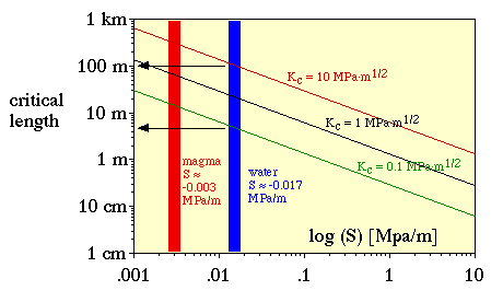
Figure A3 shows that vertical water filled fractures can reach lengths
of about 5-100 m. Above that length, such fractures become unstable and
rise rapidly, in the order of metres per second. A mobile fracture can
thus easily ascend through the crust in a matter of hours. A mobile hydrofracture
stops when the conditions of equation (A.4) are no longer satisfied. This
can be because of rock type with a higher fracture toughness is encountered
or when S decreases. The latter is probably the main reason for arrest.
At any time it is easier for a fluid to enter pre-existing fractures than
to propagate a fracture through intact rock. The presence of fractures
thus causes the dispersal of fluid into these fractures, lowering S. For
a hydrofracture to be mobile, the average pressure in the fluid must be
lithostatic. Fluid is lost to the wall rock when a fracture reaches lower
than lithostatic fluid pressures in the wall rock. Low fluid pressures
and pre-existing fractures occur above the brittle-ductile transition and
hence mobile hydrofractures are to be expected to get arrested at this
level.


