3.2.1. The crack-seal mechanism
Before discussing the processes and causes for precipitation inside a vein, it is worthwhile to briefly discuss the crack-seal mechanism. The crack-seal mechanism was first introduced by Ramsay (1980) and has quickly become the accepted mechanism for the formation of fibrous/elongate blocky veins (Cox et al. 1986, Urai et al. 1991, Kirschner et al. 1993). The mechanism itself does not dictate any fluid or solute transport mechanism, nor a specific cause for precipitation inside a vein. The essence of the crack-seal mechanism is the repeated formation of a crack which is subsequently sealed by precipitation of vein forming material inside that crack. The crack-seal cycle can be repeated hundreds of times, typically adding about 10 µm to a vein each cycle (Fisher & Brantley 1992). The crack-seal mechanism can explain many parallel wall rock inclusion trails that are often found in veins (Fig. 13 & 21). The effect of the crack-seal mechanism on the morphology of vein forming crystals (stretched / elongate blocky / fibrous) and the tracking-capability of elongate crystals is further discussed in Appendix B.
3.2.2. Vein growth without fracturing
Probably the most clear-cut case of vein growth without fluid flow,
but by diffusional solute transport is a pressure fringe adjacent to a
rigid object (e.g. a pyrite grain). The presence of a rigid object in a
deforming/stressed rock causes a perturbation of the stress and pressure
field around the object (Durney &
Ramsay 1973, Strömgård 1973, Durney 1976, Selkman 1983).
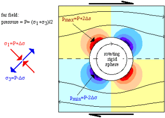
The sides of the object facing the highest compressive normal stress experience
the highest pressure, while the sides facing the lowest normal stress experience
a relative low pressure (Fig. 24). This pressure difference can drive dissolution
at the high pressure sides, diffusional transport to the low pressure sides
and precipitation there to form the pressure fringes. This process can
occur without the formation of a (thin) crack at the low pressure sides
of the rigid object. Pressure fringes are usually fibrous and generally
have no wall rock inclusions and therefore show no typical indicators for
repeated crack-sealing. However, crack-sealing can occur, as has been shown
by Lister et al. (1986)
for biotite porphyroblasts where radiator structures formed in pressure
shadows.
It may be important that pressure fringes are usually fibrous (not elongate blocky) and appear to form without any brittle failure: there are no microstructural indicators for fracturing and the stress and pressure field around the object provide the driving force for material transport and precipitation in the fringe. This supports the hypothesis that the fibrous crystal morphology may form in the absence of fracturing, as was also proposed by Taber (1918) and Mügge (1928), and more recently by Durney & Ramsay (1973), Janssen & Bons (1996) and Bons & Jessell (1997). In the absence of fractures, diffusion is the only viable transport mechanism and we may infer that fibrous veins are indicative of diffusional material transport.
Taber (1918) argued that the base of fibrous crystals must be in contact with a supersaturated solution in pores in the wall rock. Fibres "grow out of" the pores, which means accretion of new material is at the wall rock - vein interface. The work of Taber has recently been replicated by Means and Li (1995a,b) and Li and Means (1995), who produced very natural looking fibrous textures, without any fracturing. Mügge (1928) argued that the absence of growth competition in fibrous aggregates indicates the absence of an open fracture in which the crystals grew. He delineated three cases:
(1) The opening rate of the vein (fracture) is faster than the maximum potential growth rate (on fastest growing crystal faces). Euhedral crusts of crystals form.
(2) The opening rate of the vein (fracture) is slower than the maximum, but faster than the minimum potential growth rate of crystals. Growth is partly constrained and elongate-blocky crystals would form with a crystallographic preferred orientation (CPO).
(3) The opening rate of the vein (fracture) is slower than the minimum potential growth rate. The surfaces of the growing crystals remain in contact with the opposite wall rock at all times and growth competition is therefore inhibited. Fibrous crystals form without the development of a CPO.
Pabst (1931) measured c-axes orientations in fibrous pressure shadows to test the hypothesis of Mügge (1928) and indeed found that the fibres did not develop any CPO. The stretched and elongate-blocky quartz veins of Cox (1987), on the other hand, did show a CPO, which is in line with Mügge’s (1928) hypothesis that such veins fall into category (2), with the refinement by Ramsay (1980) that opening rates are not constant, but that space is created in distinct steps by repeated crack-events.
In the case of fibrous growth in pressure fringes, the driving forces
for diffusional transport and precipitation are evident: the stress and
pressure perturbation caused by the relatively rigid object. Can growth
without fracturing in other fibrous vein types be explained, when the transport
mechanism and cause for precipitation is less evident? Well developed antitaxial
fibrous calcite veins in shales are found in Opaminda Creek (northern Flinders
Ranges, South Australia). The Young’s modulus of calcite is at least about
double that of shale (Birch 1966).
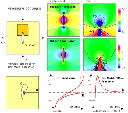
An isolated (lenticular) calcite vein therefore forms a hard object relative
to the surrounding shale and, during deformation, would (as for rigid pyrite
grains) develop a pressure gradient around itself (Fig. 25), which can
drive further growth of the vein. Such veins can then be regarded as ‘self-supporting’
pressure fringes. Propagation at the vein tips, where a strongly localised
stress perturbation occurs, lengthens the vein as it widens, which probably
enhances the process.
For this process to work, a ’seed’ vein must already be present. Many of the antitaxial fibrous veins at Opaminda Creek have a median zone that is actually blocky in texture and fibrous crystals started growing from the surface of this zone (Fig. 19). The veins may have thus started their life by another process than described above and subsequently grew wider and longer by material transfer and precipitation by a self-supported pressure gradient. It should also be noted that fibrous veins at Opaminda Creek occur as isolated lenses, but also as long (metres) and thin (cm’s) fracture-shaped veins, both of which are antitaxial and fibrous. The shape of these veins is probably related to fracturing, which may have only seeded these veins. However, the actual driving force for subsequent fibrous growth in fracture-shaped veins is not known.
3.2.3. Vein growth in fractures
Fractures are the most common sites for veins to form, as fractures provide space for precipitation and preferred pathways for fluids to flow through. Two main causes for precipitation inside fractures can be distinguished:
a) Vein-forming material is derived from a fluid that resides in both fractures and surrounding wall rock. The conditions inside the fracture and in the wall rock are different, such that a fluid that does not produce any (significant) precipitation in the wall rock does precipitate one or more minerals inside the fracture. Vein formation can then occur in the fracture by either diffusional transport in a possibly stagnant fluid or by flow of a fluid that brings local fluid from the wall rock into a vein. Again we can distinguish two cases:
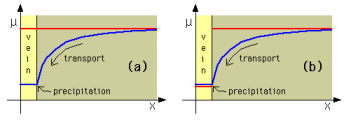
a2) The difference in conditions between fracture and wall rock cause
a difference in the chemistry of the fluid residing in fracture and wall
rock (Fig. 26.b). This could, for instance, be due to a difference in fluid
pressure in both reservoirs. Silica solubility is pressure dependent, and
therefore, we may expect that at a constant concentration of silica, fluid
may be undersaturated in a high fluid pressure wall rock and supersaturated
in a low fluid pressure fracture, where precipitation then occurs. Veins
are often associated with deformation by dissolution-precipitation creep
or ‘pressure solution’ (Durney 1976,
Rutter 1976; 1983, Raj 1982, Lehner 1990). This deformation mechanism
involves dissolution at certain sites, transport of dissolved material
and precipitation of that material at other sites. The redistribution of
material produces a change of shape of the rock: deformation. Re-precipitation
can occur pervasively in the rock, but can also be localised, in which
case veins form (Beach 1977, Winsor
1984, Cox et al. 1986, Fisher & Brantley 1992, Gratier
et al. 1993) (Fig. 27).
Minerals precipitating in a fluid filled fracture grow into an open fluid, even though there may only be a few microns of free space, before the other side of the fracture is encountered. The shape of the crystals is then determined by the growth competition of different minerals and the competition between crystals with different crystallographic orientations. The resulting texture in the vein depends on several factors (Urai et al. 1991):
- the morphology of the fracture surface (smooth, rough);
- the width of the fracture;
- the growth habit of the vein forming mineral(s).
The effects of the different factors are discussed and illustrated in more detail in Appendix B. Microscopic morphologies that result from crack-sealing are typically elongate blocky and stretched crystals. The first form when repeated fracturing occurs on the same fracture surface, while the second is the result of repeated fracturing along different surfaces.
3.2.4. Coupled fracturing and fluid flow
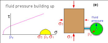
High fluid pressure, close to lithostatic, can only form in a low permeability
regime which prevents rapid drainage of the overpressured fluid (Sibson
et al. 1975, Nur & Walder 1992). Close-to-lithostatic
fluid pressures therefore are generally found only at deeper levels in
the crust, roughly below the brittle upper crust. As mentioned above, high
fluid pressure can create high permeability through fracturing - especially
when helped by deformation (Cosgrove
1993). The ensuing high permeability allows draining of fluid, which
brings the fluid pressure down towards hydrostatic levels. Closure of dilatant
fractures and sealing of fractures by precipitate reduces permeability
and fluid pressures eventually rise again. This cyclical behaviour of rising
fluid pressure until sudden fracturing, release of fluid ("burping") and
reduction of fluid pressure is known as "fault valve behaviour" or "seismic
pumping" (Sibson et al. 1975,
Nur & Walder 1992, Thompson 1997, O'Hara & Haak 1992) (Fig.
28). It is generally used to explain extensive veining, such as the gold-bearing
quartz veins in mesothermal gold deposits (e.g. Victorian and Yilgarn gold
fields in Australia (Cox et al.
1986, Sibson & Scott 1998)).
Changes in temperature (Eisenlohr
et al. 1989) and pressure (Vrolijk
1987, Henderson & McCaig 1996) are the primary causes for precipitation
of vein forming material from a fluid that is flowing through fractures.
Chemical interaction with the wall rock and mixing of different fluids
are other possible causes (Boullier
et al. 1994), but as veins occur in almost any type of rock,
these can not be the main reason for precipitation. As quartz is the main
mineral in large fracture hosted vein sets, the discussion below focuses
on the solubility of silica. Silica solubility is primarily dependent on
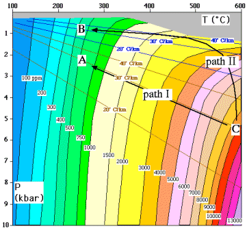
temperature (Fig. 29), except at high temperature and low pressure, where
the solubility becomes strongly pressure-dependent. The solubility of silica
is about 500 ppm in pure water that is at a lithostatic pressure of about
200 Mpa at about 250°C (consistent with a depth between 5 and 10 km
and a geothermal gradient in the order of 30°C/km, point A in Fig.
29). Dropping the fluid pressure to hydrostatic pressure (point B) reduces
the solubility to about 400 ppm. The drop in pressure thus causes about
20% of dissolved quartz to precipitate and 10,000 kg of water is needed
for every kg of vein quartz. The pressure sensitivity is even smaller at
lower temperature. The large amount of fluid needed (fluid/rock ratio about
10,000 and at least 1000) is a problem. One source for the fluid can be
metamorphic dewatering at deeper levels. Another possibility is recycling
of water by pumping fluid in and out of the rock ("seismic pumping", Sibson
et al. 1975) or convective flow, that allows the fluid multiple
passes through the same veins (Etheridge
et al. 1983; 1984).
Metamorphic dewatering produces hot water at depth. Solubility of silica at source conditions of the fluid are high, in the order of >10,000 ppm (point C in Fig. 29). Cooling of the fluid as it flows upwards causes almost all of the dissolved quartz to precipitate at deep levels (Connolly 1997). One would thus expect most quartz veins to form just above the level of dewatering. However, extensive quartz veining is usually found at much shallower levels. It seems that metamorphic dewatering and normal advective (Darcian) upward flow of fluid cannot explain the formation of extensive vein sets at shallow levels: more than 90% of the dissolved quartz would have precipitated before reaching the veining level as flow is too slow to maintain any significant elevated fluid temperature.
Metamorphic dewatering can, however, produce extensive quartz veining at or just above the brittle-ductile transition, without significant quartz precipitation at deeper levels, if the fluid can rise fast enough not too cool (much) before reaching the brittle-ductile transition. Mobile hydrofracturing provides the mechanism for such a rapid rise (Appendix A). The rise of water filled fractures at rates in the order of metres per second allows the water to stay hot until arrest in brittle levels of the crust (Bons in press b). Upon arrest (point A & B in Fig. 29), the water then still contains several thousands ppm of silica, which is immediately dumped as the water cools to the much lower ambient temperature. As is explained in Appendix A, arrest occurs in the base of the brittle region, where the fluid can enter pre-existing fractures or where a low (hydrostatic) fluid pressure causes leakage of the fluid into the wall rock. In the latter case, one can expect significant wall rock alteration to occur.
Shear zones on small scales to crustal scales focus fluid flow, due to their enhanced permeability, either on the microscopic scale (dilatant grain boundaries or microfractures) or the macroscopic scale (fractures) (Connolly 1997, Thompson 1997). Many shear zones show evidence of enhanced fluid flow in the form of retrograde mineral reactions that involve hydration and/or the presence of veins (Rutter & Brodie 1985, Dipple & Ferry 1992, O'Hara & Haak 1992). Shear zones are also the preferred pathways for mobile hydrofractures, as they provide a relatively weak zone for hydrofracture propagation and, in case of crustal scale shear zones, provide a continuous pathway through the crust for ascending fluids. Many extensive vein systems are therefore associated with major fault and shear zone systems (Eisenlohr et al. 1989).
Veined fractures are usually regarded as the product of fluid flow. Hence, their study can provide insight in how fluid flows. This view should be reconsidered: veins that form from mobile hydrofracture arrest may tell us more about how fluid failed to flow. This philosophical point can perhaps best be explained with the analogy with granites: the shape and structures of granite bodies tell us most about the emplacement mechanism (stoping, ballooning, etc.) and much less about the mode of transport of granite melt (Clemens 1998).
Significant supersaturation, open fluid-filled fracture space and repeated fracturing are characteristic for both veins that form from extensive flow through fracture networks and by arrest of mobile hydrofractures. Elongate blocky textures and evidence for crack sealing can be expected. Significant supersaturation can cause ongoing nucleation of precipitating minerals, which produces a blocky texture.
