3.4
VISUALIZING ORIENTATIONS
top / contents / section3/ pages -- 3.1 -- 3.2 -- 3.3 -- 3.4 -- 3.5 -- 3.6 -- 3.7 -- 3.8 -- 3.9
The c-axis orientation image (COI)

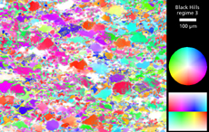
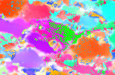
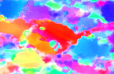
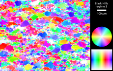
To create a c-axis orientation image (COI), two channels (azimuth and inclination image), and a 2-D colour look-up table (CLUT) are necessary. The CIP-Standard CLUT assigns one unique colour to each of the 180*180 possible orientations. Two problems arise: 1. the CIP-Standard CLUT has a colour discontinuity between incl=90° and incl =91°. Thus, axes dipping slightly above and slightly below the image plane appear with a maximum colour contrast (e.g. red-cyan) while in reality the orientational difference is very small. 2. The most critical part in the CIP calculation is the derivation of the correct inclination , i.e., the decision if axes dip above or below the image plane. This step often introduces some noise in the inclination image, causing the corresponding COIs to be spotted. Both of these problems are overcome if the symmetric CIP-Spectrum CLUT is used.
Left:
Two c-axis orientation images (COIs) of experimentally deformed Black Hills quartzite, using the CIP-Standard and the CIP-Spectruzm CLUT
Below:
- Detail of COIs


