3.6
VISUALIZING ORIENTATIONS
top / contents / section3/ pages -- 3.1 -- 3.2 -- 3.3 -- 3.4 -- 3.5 -- 3.6 -- 3.7 -- 3.8 -- 3.9
Making masks from the error and background images

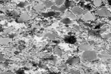
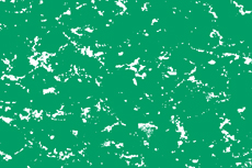
In order to select certain data from a given c-axis orientation image, it may be necessary to mask the COIs. Masks may be derived in a number of way, here the design of an error and scratch mask is shown. On the basis that non-uniaxial minerals yield high errors, an error mask may help to eliminate feldspar grains form the analysis. For CIP, the masking part has to be non-zero (here=black).
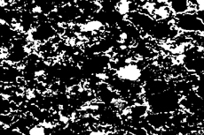
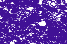
A mask blocking out sites with high CIP errors is obtained by thresholding the calculated error image. For a dust&scratch mask, a plane polarized image of the thin section is recorded. Scratches, holes, glue drops, dust particles, grinding powder, general dirt, etc. appear black and can be thresholded. (A further use fo this this type of background image is to correct for uneven lighting.)
Left, from top to bottom:
- error image
- thresholded error image
- thresholded dust&scartch mask
Below:
- combined error and dirt mask


