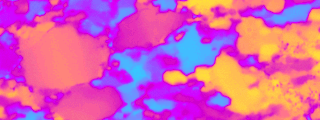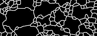

The aim of the procedure described below is to identify grain boundaries on a thin section, and to represent those in the form of a grain map (in image processing, this is called image segmentation).
|
|
|
The following programs and procedures are used:
The Lazy grain boundary detection uses gray scale input images and it is assumed that - in some way - the gray scales represent different crystallographic orientations, in the sense that a rapid change of crystallographic orientation is portrayed by a rapid change of gray value. For better results, more than one image is used per area of analysis, for example, various orientations of polarizer/analyzer with respect to the thin section may be used. The basic idea is to combine the most significant information from different images rather than trying to get all information out of one.
The procedure described in the following uses misorientation images as input. It is the "standard procedure" for quartzites. The resulting grain boundary maps are designated by the ending "cuogu-z-3tji" which is short for the sequence of key strokes that are used to carry out the segmentation. For most steps in the procedure, a number of alternatives are possible. From my experience, the "standard procedure" works best for quartzites, for other rock types and other input images, other combinations of key strokes may yield better results (and maybe new macroes have to be written....).
GRAIN BOUNDARY DETECTION step 1 - step 2 - step 3 - step 4 - step 5 - step 6/7 - step 8/9