1.1
WHAT IS ORIENTATION IMAGING ?
top / contents / section 1 / pages 1.1 -- 1.2 -- 1.3 -- 1.4 -- 1.5 -- 1.6 -- 1.7
Introduction
Imaging

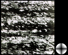
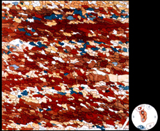
Micrograph (crossed polarizers) and
Achsenverteilungs-Analysen (AVA) of
quartzite
The process of imaging refers to colour-coding physical information on a two-dimensional image plane. For example, if the physical information is the brightness variation on an illuminated object the image is a regular black and white photograph. If the physical information is the concentration of an element or the surface temperature the resulting image would be a chemical map or a thermograph. Many other examples could be given. Here we are interested in obtaining orientation images, i.e., maps of crystallographic directions, more specifically colour-coded maps of the optical axis orientations of uniaxial minerals (quartz, calcite, ice, norcamphor, etc.).
The first orientation images were produced by Bruno Sander and his collaborators in the early fourties. In order to perform what they called an "Achsen-Verteilungs-Analyse" (AVA), they placed a given microstructure in the optical microscope, drew a grain boundary map, measured the c-axis orientation of each of the grains with the Universal stage, and assigned colours to certain regions in the pole figure. Using this colour-code the grainboundary map was filled.
Nowadays we can produce such orientation images by means of digital image processing. Not only is this a much faster way of doing it, it is also a more precise and rigorous way. First of all, the orientation is determined at each point of the image and not only once per grain, secondly, we may also derive misorientation and deformation gradient images, thirdly we may select texture domains interactively which means that we can perform strain- shape- and grain size analysis as a function of crystallographic orientation.
Look-up tables and conoscopic images

1-D look-up table

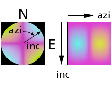
conoscopic image and 2-D look-up table of quartz
The concept of look-up tables (LUTs) is going to be of prime importance.
The typical LUT is one-dimensional assignment of colours or grey values to input values. Here we will use two-dimensional LUTs to assign colours to pairs of azimuth and inclination values.
We will consider the conoscopic image as a look-up table (more precisely, as the stereographic projection of a look-up table) from which we derive the orientation of the optical axis of any pixel in the image.
We will adopt the following conventions: Orientations of the c-axes are given in terms of azimuth and inclination, the principal directions being N (North), E (East), and H (Heaven) with respect to the plane of the thin section, i.e., the image plane. North-South is vertical, East-West is horizontal, Heaven-Hell is normal to the image plane. The azimuth is measured from N = 0° clockwise to South = 180°, the inclination from Heaven = 0û downwards to Hell = 180°. An axis oriented East-West parallel to the plane of the thin section would be denoted 90/90, one striking NW/SE, dipping 30° below the plane of the thin section would be denoted 135/120.
