1.4
WHAT IS ORIENTATION IMAGING ?
top / contents / section 1 / pages 1.1 -- 1.2 -- 1.3 -- 1.4 -- 1.5 -- 1.6 -- 1.7
... using crossed polarizers and lambda plate


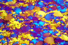
The quartzite is shown under crossed polarizer conditions with the lambda plate inserted. Grains or pixels that appear magenta coloured (first order red) can have any c-axis orientation parallel to the East-West or the North-South plane, i.e., they can have any inclination provided the azimuth is 0° or 90°. Grains that appear blue have c-axes that strike NE-SW (...BURP...blue upper right positive), those which appear yellow have axes striking NW-SE.
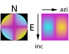
The colour-orientation relation is represented by the conoscopic image. The orthogonal representation of the look-up table is shown on the right.
The number of possible c-axis orientations for any given interference colour is reduced with respect to the previous representation (crossed polarizers only), but still there is no unique representation.
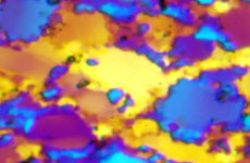
In the previous micrograph, the little chipmunk appeared nearly white, implying that its c-axis strikes either NW-SE or NE-SW at an inclination very close to the plane of the section. Now, the chipmunk appears yellow, that means that the c-axis of the chipmunk strikes NW-SE. The yellow colour is very bright, indicating again that the axis must have an inclination closer to 90° than 0° / 180°.
Left, from top to bottom:
- Experimentally deformed Black Hills quartzite under crossed polarizer conditions and lambda plate
- conoscopic image and look-up table for crossed polarizer conditions and lambda plate
- the chipmunk has blue eyes!