1.5
WHAT IS ORIENTATION IMAGING ?
top / contents / section 1 / pages 1.1 -- 1.2 -- 1.3 -- 1.4 -- 1.5 -- 1.6 -- 1.7
... using crossed polarizers, lambda plate and narrowband infrared filter


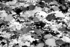
The quartzite is shown under crossed polarizer conditions with the lambda plate and a narrow band filter (transmission: 700±9 nm, near infrared) inserted. This filter renders frist order yellow as white, first order red as grey and first order blue as black.
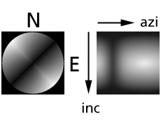
Again, the brightness-orientation relation is represented by the conoscopic image. The orthogonal representation of the look-up table is shown on the right.
By inserting the filter, the interference colours (3 channels) are mapped uniquely into a grey value image (1 channel). As in the previous case the number of possible c-axis orientations for any given grey value is reduced with respect to the crossed polarizers conditions, but still there is no unique representation.
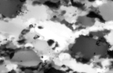
The little chipmunk appears nearly white, indicating that its c-axis strikes NW-SE at an inclination very close to the plane of the section. From the point of view of colour-coding (or grey-coding) the c-axis orientations, there is no advantage over the previous case except that the storage space for a monochrome image is less than that of a colour image.
Left, from top to bottom:
- Black Hills quartzite under crossed polarizer conditions, lambda plate and narrow band interference filter (660 nm).
- conoscopic image and look-up table for crossed polarizer conditions, lambda plate and 660nm interference filter.
- the "infra-red"chipmunk.