1.6
WHAT IS ORIENTATION IMAGING ?
top / contents / section 1 / pages 1.1 -- 1.2 -- 1.3 -- 1.4 -- 1.5 -- 1.6 -- 1.7
... using circular polarization: crossed polarizers and two quarterwave plates


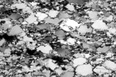
The quartzite is shown under so-called circular polarization conditions with crossed polarizers and two quarter wave length plate (1/4 lambda plates) inserted. Circular polarization yields an inclination image, where the grains appear dark if the c-axes are normal to the plane of the section, and white if the c-axes are parallel to it. Circular polarization is not sensitive to the azimuth of the c-axis (no use turning the microscope table...)
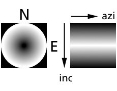
Again, the brightness-orientation relation is represented by the conoscopic image. The orthogonal representation of the look-up table is shown on the right.
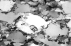
The little chipmunk appears nearly white, indicating that its c-axis lies very close to the plane of the section. In as much as some of the grain boundaries (probably the wider ones) are optically isotropic, they appear black
Left, from top to bottom:
- Experimentally deformed Black Hills quartzite under circular polarization (crossed polarizers and two 1/4 lambda plates).
- conoscopic image and look-up table for circular polarization.
- the circularly polarized chipmunk.. does not seem to mind it