Lecture 5- Microstructures and Deformation Mechanisms
 CET/UWA Microstructure Course
| TOC
| Lecture 1
2
3
4 a
b
5 a
b
| Lab 1 a
b
c
2 a
b
c
3 a
b
4 a
b
5 a
b
| Glossary Table
1
2
3
4
5
Index
| GEOS5505 Lab 1
|
1) Introduction
We can define microstructures (based in
part on a Hobbs, Means & Williams
1976 definition) to be:
"the small-scale arrangement of geometric and
mineralogical elements within a rock."
This of course begs the question as to what small-scale means, and we
will be going on a tour of microstructures in this course at increasing
scales:
Atomic scale (eg defects) ->
intra-crystalline (eg twinning) ->
inter-crystalline (eg porphyroblasts) ->
multi-grain interactions (eg shear bands, continuum mechanics)
Microstructures are also called fabrics by some people, or microfabrics.
2) Why do we study microstructures?
-
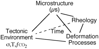
To establish the link between process, environment & microstructure
via general constitutive equation eg Dorn 1957
-
The (Micro)structure is a function of the competing processes in a rock:
(PROCESS RATE=DRIVING FORCE*KINETICS) as they act on an initial (Micro)structure. By understanding this relationship we can interpret microstructures in terms of the history of temperature (T) , pressure (s), the CO2 fluid pressure (�CO2) and other boundary conditions that control both the driving force and the kinetics
-
To provide evidence of deformation processes, which in turn provides:
-
evidence of rheology during deformation, which is important for geodynamic
interpretation
-
interpretation of deformation history
-
evidence of metamorphic environment
-
interpretation of seismic anisotropy
-
microstructural geochemistry
3) How do we study microstructures
See Introduction to  Urai & Jessell 2001 for discussion of different techniques applied to recrystallisation.
-
Field work
-
measurement of cleavages & lineations, etc (Hobbs,
Means & Williams 1976)
measurement of numerous types of sense of shear (aka kinematic) indicators Passchier, C.W. & Trouw, R.A.J. 1996.
-
Observation
-
microscopy - optical thin section analysis
-
SEM - Scanning Electron Microscope - observes surfaces only c.f. reflected light
microscopy
-
TEM - Transmission Electron Microscope - thin foil samples c.f. transmitted light
microscopy
-
Cathodoluminescence (CL)-displays trace chemical variations
-
Quantitative analysis
-
Crystallographic Preferred Orientations (CPO)
-
Grain Shape Foliations (GSF)
-
Grain Size Distributions
-
AVA ("Achsen-Verteilungs-Analyse": mapping crystallographic orientations across a thin section) See
 Heilbronner 2001 for an image processing based technique for mapping microstructures
-
Stable isotope studies
-
Experiments
4) Deformation Mechanisms & Processes 
a) Definitions:
Deformation Mechanisms are processes that lead to a change in shape of rock
- There are many types of deformation mechanisms which have been recognised in rocks and other crystalline materials, such as ceramics and metals. We provide a table of deformation mechanisms and processes and the effects they have on microstructure.
There are many other processes, often deformation related, that don't lead to change in shape
- grain boundary migration
- rotation recrystallisation
- metamorphic reaction
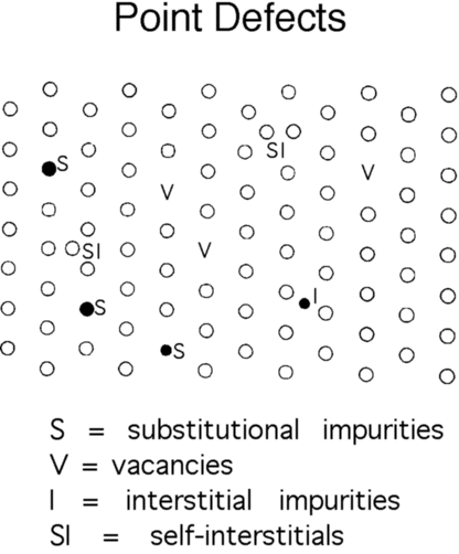
b) Defects- imperfections
in the structure of a crystal, and can be 0-dimensional, 1-dimensional
or 2-dimensional
i)Why are defects so important?
-
They can speed up the process of crystal growth by orders of magnitude
(geometry)
-
The distorted crystal lattice around defects provides rapid diffusion pathways
within crystals (geometry)
-
They are intimately involved in several deformation mechanisms (kinematics)
-
Provide a driving force for many deformation processes (dynamics)
-
Can weaken the strength of a crystal by several orders of magnitude (dynamics)
-
The movement of dislocations can lead to the formation of crystallographic
preferred orientations
ii) Defects in crystals:
-
Point 0-D known as point
defects
-
vacancies, interstitials, discrete 2nd phase
-
Line: 1-D known as dislocations


-
dislocations are important for their:
-
geometry - each dislocation represents a small angular distortion of the
lattice, a lot of them together can result in a curved crystal lattice,
or a sharp misorientation across a boundary. Dislocations can also act
as fast diffusion pathways.
-
kinematics - the movement of dislocations results in the accumulation of
deformation within a crystal. The deformation of a material by the movement
of dislocations is known as crystalline plasticity
-
dynamics - the distortion around a dislocation provides an energy source
for other processes such as grain boundary migration.
-
Plane: 2-D boundaries between different grains or parts of grains
-
grain boundaries, twins, internal phase boundaries, stacking faults
- Grain boundaries will be discussed in much more detail in Lecture 2.

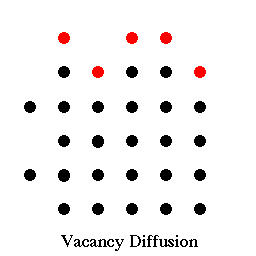
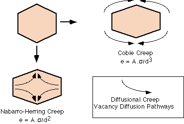
c) Movement of Point Defects: Coble creep & Nabarro-Herring
creep  :
:
these two processes involve the non-random motion of point defects and can cause a change in shape of a crystal, and are thus deformation mechanisms. The movie just below shows vacancies moving through a crystal, and this is known as Nabarro-Herring Creep. If the vacancies diffuse around the grain margins, it is known as Coble Creep. Click on the picture below to see how vacancy diffusion works.

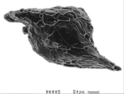
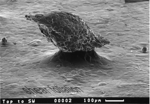
The images below are of detrital quartz grains in a calcite
shear zone. they are single crystals with no evidence of rotation recrystallisation in
wings. The lace network on surface reflects cte-cte-qtz triple junctions. They probably
formed as a result of Coble and/or Nabarro-Herring creep. Images courtesy of
Michel Bestmann (michel@geol.uni-erlangen.de
Institut für Geologie und Mineralogie, Schloßgarten 5, 91054
Erlangen, Germany)
d) Direct Observation of dislocations:
- Etch pits (acids preferentially etch intersection of dislocation with crystal surface)
- Decoration by heat treatment (trace elements precipitate on dislocations)
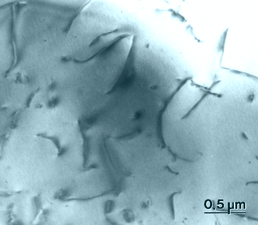
- Transmission Electron Microscopy (TEM)- a very thin 0.2-3 µ specimen is required
i) Bright field image. This TEM image shows the interior of a quartz grain experimentally deformed by Alice Post whilst doing her PhD at Brown University.
 iii) Undulose extinction demonstrates the effect of large numbers of dislocations
producing a curved lattice
e) Movement of dislocations:
-
Slip Systems: any given mineral will favour
dislocation motion in particular crystallographically controlled directions.
The plane in which the dislocation moves is called the slip plane, and
the direction in which it moves is called the slip direction.
-
Burgers vector: the length of the dislocation
of the crystal lattice caused by a single dislocation is known as the Burgers
vector, and this will be constant for any one slip system.
-
The Critical Resolved Shear Stress (CRSS)
is the stress (as resolved onto the slip plane in the slip direction)
needed to cause dislocation motion, ie break shortest bonds. Typically it decreases with increasing
temperature for all slips systems in a mineral, however it may not decrease
at the same rate for all systems.
-
edge dislocation movement results in part
of the crystal moving perpendicular to the dislocation line

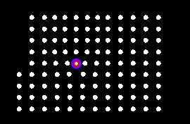 Dislocation glide (edge dislocation)
-
screw dislocation movement results in part
of the crystal moving parallel to the dislocation line

-
climb is a diffusive process whereby
the dislocation line moves perpendicular to the dislocation line direction,
but within the plane of the extra half-plane of atoms.

-
stacking faults- are planar features where a
-
loops if you take a dislocation line and follow
it round and it joins back up with itself, this is known as a loop, and
is by its nature made up of a combination of screw and edge dislocations,
with a cylindrical volume of "slipped" crystal within the loop. As the
loop grows, the volume of slipped crystal thus grows with it.

-
Frank-Reed sources are "loop generators" that
occur as impassable defects in a crystal hold up the passage of a dislocation.
If two such defects occur as neighbours, an automatic loop generator is
formed. This is what a dislocation Frank-Read source looks like. See Dislocation dynamics section in Lab 1 for further examples. This simulation shows one inclined slip plane with loops being generated continuously.
-
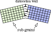
tilt boundaries- sub-grain boundaries made
up of arrays of edge dislocations
-
twist boundaries- sub-grain boundaries made
up of arrays of screw dislocations
f) Rheology of dislocation glide:
r =dislocation density = no of dn
lines per cm2 or total line length per cm3
-
near perfect artificial crystal 102cm-2
-
annealed or as grown crystal 105cm-2
-
cold worked crystal 108 to 1011cm-2

this is OROWANS EQN, where V = ave mobile dislocation velocity

at low V, V is proportional to the stress which
gives:

g)Twinning 
Unlike dislocation glide, movement of a twin boundary significantly
and permanently alters the orientation of the crystal. The orientation
of the twin plane, and the misorientation across the twin boundary will
be precisely the same for any particular type of twin, and the process
of twinning is essentially instantaneous, there is not a gradual change
in crystallographic orientation, as the twin boundary moves across a region,
the crystal lattice flips, and a discrete increment of deformation is attained.
Further deformation of the grain may cause more material to become twinned,
but it does not further deform the twinned volume (at least not by the
same type set, other twins, or other mechanisms may of course be activated).
Deformation twins can often be distinguished from growth twins (that form
during crystal growth) by being thinner, and having wedge shaped terminations. They are particularly important in the low temperature deformation of calcite, and the deformation of plagioclase.
Here is a movie of twin development in bischovite, a hydrated magnesium salt, made by Janos Urai.

h) Kinking 
Kinking superficially looks like twinning, however the relationship
between the misorientation across a kink band boundary, and the orientation of the kink band boundary and the amount of deformation caused by the kink are not predictable. Micas often deform by kinking, which involves slip on the basal plane.
h) Grain boundary sliding 
The movement of one grain past another, in pure material this may be accomplished by dislocation or diffusive mechanisms.
A beautiful molecular dynamics simulation of copper nano-crystals undergoing grain boundary sliding during vertical extension was performed by Jakob Shiotz (J. Schiotz, F. D. Di Tolla, and K. W. Jacobsen, Nature, 391, 561 (1998)). Here the sphere shading relates to the local crystal structure: White atoms are in a perfect face centred cubic environment. Light gray atoms are in local hexagonal close packing order, which for example corresponds to stacking faults. Atoms in any other environment (in grain boundaries and dislocation cores) are colored
dark grey.
i) Other deformation processes:
- neighbour switching
The switching of grain relationships (needs grain boundary sliding and diffusion to cooperate to allow this).

-
rigid body rotation-
rotation of grain without any internal deformation. A ball undergoes
rigid body rotation (or bulk rotation) when you roll it along the ground. Very rigid grains in a soft matrix will typically rotate in non-coaxial deformation regimes (see discussion on porphyroblasts in lecture 4). Similarly a feldspar lath in a granite melt can rotate with essentially no internal deformation if the melt is sheared.

-
fracture- the brittle
cracking of a mineral, often followed by sliding on or pulling apart of
the fracture surfaces

-
phase change- a
change in the crystallography of the crystal, without a change in its bulk
chemistry.
-
Pressure Solution- The long-range (multiple grain) diffusive mass transfer of material. See lecture 5.

j) Deformation mechanism maps & Rheology 
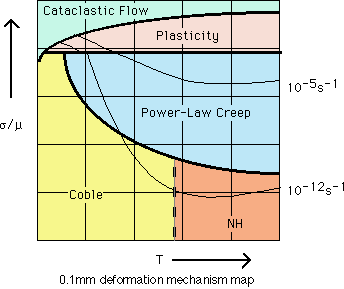
These are graphs in typically stress-temperature space (but also grain
size-temperature and others) which show which deformation mechanisms dominate
under which conditions FOR A PARTICULAR MINERAL. They are contoured in
strain rates, showing the strain rate that would be achieved by that process
alone under the appropriate conditions. They only show dominance in terms
of which mechanism is likely to account for the most strain, the label
in any particular field does NOT mean that no other mechanism or process
is active, and it does NOT mean that the microstructural development will
be controlled by that labeled mechanism, in fact it does not even mean that the deformation
mechanism is the dominant process in terms of microstructural evolution. It would be nice if we had general Microstructral
process mechanism maps, an example of which is shown at the end of Lecture 3.
 CET/UWA Microstructure Course
 CET/UWA Microstructure Course
![]() Urai & Jessell 2001 for discussion of different techniques applied to recrystallisation.
Urai & Jessell 2001 for discussion of different techniques applied to recrystallisation.
![]()


![]()
