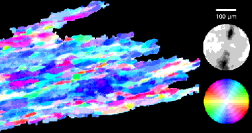
The aim of Computer-integrated polarization microscopy (CIP) is to generate c-axis orientation and misorientation images from thin sections. The method has been described (Panozzo Heilbronner & Pauli, 1993 & 1994) and applications have been published (Pauli et al., 1996, Herwegh et al., 1997, VanDaalen et al., in press, references ).

Technical requrements |
Set of input images |
Software |
Set of output images |
Basically, there are two CIP procedures: one routine procedure, where it is assumed that all calibrations have been performed, and one calibration procedure, which has to be carried out when new equipment and new material is used. The follwing describes the routine procedure.
|
2 - Acquiring images |
|
|
10 - SUMMARY CIP |