ABOUT ORIENTATION IMAGING
top / contents / section 1 -- section 2 -- section 3 -- section 4 -- section 5 -- section 6 -- appendix 1 -- appendix 2
How to use this contribution
"OPTICAL ORIENTATION IMAGING" is written in HTML and consists of a number of web pages which can be viewed with any regular browser. Still the design of the contribution is basically a running text which takes the reader through a sequence of six sections that follow each other. These sections are not meant to convey scientific content, rather they are meant to be demonstrations of what can be done with optical orientation imaging, of how this technique can be used in the earth materials research. It is hoped that they stimulate the reader to try using this tool. It is also possible to acces the folders directly and to work with the images directly.
File Structure
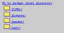
The text and image files of "OPTICAL ORIENTATION IMAGING" are stored in a folder "OrientationImaging". This folder contains four folders: "CLUTs", "figures", "images", and "text" (A list of all microstructure images in original TIFF format can be found here). The "text" and "figures" folders are subdivided into sections,the subfolders of the "images" folder refer to topics or specific samples. The starting page is in the folder "text": file://OrientationImaging/text/0000.html.
Dragging the folders into the open window of Netscape will display this file structure.

You can browse through the folders and copy whichever file seems interesting.
Organization of sections
Each section is colour-coded, the pages are numbered and displayed at the top of each page. The reader can page through each section or go to the index of the section by clicking on the appropriate page number. top and contents are links to the title page and the table of contents rspectively. From each page, one can get to the top of the section and the table of contents but not to the indivual pages of the other sections; the about page (the one you are reading right now) can only be reached via the title page.
Organisation of appendices
The appendices are guides to the images, to software and to references.
section 1 - WHAT IS ORIENTATION IMAGING ?
- 1.1 Imaging, look-up tables and conoscopic images
- 1.2 Orientation imaging through the light microscope
- 1.3 ... using crossed polarizers
- 1.4 ... using crossed polarizers and lambda plate
- 1.5 ... using crossed polarizers, lambda plate and narrowband infrared filter
- 1.6 ... using circular polarization: crossed polarizers and two quarterwave plates
- 1.7 Optical orientation imaging
section 2 - CALCULATING THE PRIMARY IMAGES
- 2.1 Setting up the microscope, the scanner and the computer
- 2.2 Recording the input images
- 2.3 Checking the input
- 2.4 Calculation of azimuth, inclination, and error images
- 2.5 The azimuth image
- 2.6 The inclination image (amplitude)
- 2.7 The inclination image (circular polarization)
- 2.8 The error image
- 2.9 The misorientation images
- 2.10 The orientation gradient images
- 2.11 The c-axis polefigure
section 3 - VISUALIZING ORIENTATIONS
- 3.1 Colour-coding the azimuth image
- 3.2 Colour-coding the inclination image
- 3.3 Checking the inclination image (cirpol)
- 3.4 The c-axis orientation image (COI)
- 3.5 Various colour look-up tabless (CLUTs) for the c-axis orientation image
- 3.6 Making masks from the error and background images
- 3.7 Principal misorientation images
- 3.8 Misorientation with respect to reference direction
- 3.9 Analysis of orientation gradient images
section 4 - ORIENTATION IMAGES OF EXPERIMENTALLY DEFORMED ROCKS
- 4.1 Starting material: Black Hills quartzite and Heavitree quartzite
- 4.2 Regime 1, 2 and 3 of dynamic recrystallization
- 4.3 Partial textures of regime 1, 2 and 3 of dynamic recrystallization
- 4.4 Annealed microstructures of regime 1, 2 and 3 of dynamic recrystallization
- 4.5 More detail on regime 3 of dynamic recrystallization
- 4.6 Making use of sample heterogeneity
- 4.7 Dynamic recrystallization of quartzite along deformation gradient
section 5 - ORIENTATION IMAGES OF NATURALLY DEFORMED ROCKS
- 5.1 Quartz mylonite from the Simplon fault zone
- 5.2 Quartz mylonite from the Corvatsch (Christian Pauli)
- 5.3 Quartz veins from the Glarus thrust (Mirjam VanDaalen
- 5.4 Quartz veins from the Tonale fault (Michael Stipp)
- 5.5 ...more on the quartz veins from the Tonale fault
- 5.6 Carrara Marble (Nils Oesterling)
section 6 - WHERE CAN WE GO FROM HERE ?
- 6.1 Grain boundary detection based on misorientations
- 6.2 Grain size sensitive texture analysis
- 6.3 Grain size analysis
- 6.4 Comparing CIP and EBSD
- 6.5 Shape - texture relations
- 6.6 Misorientation analysis of grains undergoing dynamic recrystallization
- 6.7 Misorientation analysis of host grain - recrystalled grain relation
- 6.8 Misorientations at grain boundaries of "flat" orientation images
appendix 1 - LIBRARY OF ORIENTATION AND MISORIENTATION IMAGES
- A1.1 Micrographs, circular polarization
- A1.2 Orientation images
- A1.3 Input images
- A1.4 List of image sets
- A1.5 List of topics
appendix 2 - SOFTWARE, LOOK-UP TABLES AND REFERENCES
- A2.1 Lazy stack
- A2.2 Lazy LUT
- A2.3 Lazy grain boundaries
- A2.4 StripStar
- A2.5 Colour look-up tables
- A2.6 References